Introduction
Traditionally, with IOS, working inside of a VRF is great joy and fun. As long as your traffic never needs to leave the VRF and is perfectly content never seeing whether the grass truly is greener on the other field. I mean, the other VRF!
The moment traffic needed to leave the VRF, to put it gently, it became a bit of a pain. Every feature worked differently across VRFs! NAT needed NVIs (RIP NVIs) and route leaking was a rabbit hole and a half!
Fortunately, on IOS-XE, there’s a great new feature called VASI that helps end this madness and restore ORDER to our inter-VRF glory! Or, in other words, it makes working with inter-VRF forwarding a heck of a lot easier!
Plus, I guess there’s a certification out there from Cisco that tests on VASI! I’m lookin’ at you, CCIE EI candidates!
Alright, let’s get started!
Lab Setup
Our lab for this post is going to be very complicated, so pay close attention!
We have two “end hosts” (H1 and H2) connected to Gig1 and Gig2, respectively, on a virtual Cat8000 router (R1). Between you, me, and the fence post though, those hosts are just virtual IOS 15 routers!
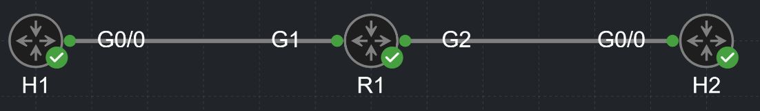
Figure 1: Here is the lab we will be working with!
Like I said, reeeaalllyyyyy complicated… 😉 😁
The IP addressing we’re using in the lab is:
- R1 and H1: 10.0.1.0/24 (R1 is assigned 10.0.1.1 and H1 is assigned 10.0.1.2)
- R1 and H2: 10.0.2.0/24 (R1 is assigned 10.0.2.1 and H2 is assigned 10.0.2.2)
H1 and H2 have default routes towards R1, so we don’t need to worry about routing on the host devices.
Oh, yeah, since we’re dealing with VRFs here I guess we should also invite VRFs to the party, huh?
R1 is configured with a VRF called H1 that contains…you guessed it, H1! And I suppose you can guess what the other VRF is called and what it contains (hint: it’s VRF H2.)
Forwarding Inter-VRF Traffic: Route-Leaking
Let’s suppose we have a really simple requirement:
- Ping between H1 and H2
Normally, this would be simple! However, we obviously have a bit of an issue here seeing as the two interfaces are in a different VRF.
We can see that in the fact that our pings aren’t going across!
H1#ping 10.0.2.2
Type escape sequence to abort.
Sending 5, 100-byte ICMP Echos to 10.0.2.2, timeout is 2 seconds:
.....
Success rate is 0 percent (0/5)
Now, if you’re a VRF aficionado (VRF connoisseur?), you’ll likely know of a technique known as route leaking. For the rest of us, route leaking is a way that we can take routes inside of one VRF table and “leak” them to the routing table of another VRF.
This works because there is nothing actually stopping us from forwarding traffic across these interfaces in the data plane (i.e., there is no filter.) The only thing the VRFs are currently doing to prevent traffic forwarding between H1 and H2 is each VRF’s lack of routing visibility of the subnets contained inside of the other VRF’s routing table.
For our demonstration today, we’ll be using the “traditional” method of route leaking, using MP-BGP inside of our VRFs and import/export route-targets. A common misconception is that, on IOS, you can only use route-targets to perform route leaking across routers. However, you can also use route targets to leak routes between VRF tables on the same IOS router! This works because the route targets get affixed (as BGP communities) to the BGP routes as they get installed into the BGP Local-RIB, which is where the route leaking happens from. You need three conditions to be true for this:
- You need the appropriate RT configurations on the VRFs (i.e., one VRF has to be exporting the RT that the other VRF is importing, and vice versa)
- BGP must be enabled on the VRF
- The networks you want to route leak must be injected into BGP (i.e., via the
networkcommand or redistribution)
You can do this using the route-replicate command as well within each VRF too, a command that was released during the EVN era, but we’ll stick with the more common way of doing route leaking.
Here’s the configuration on R1 to leak the routes between the H1 and H2 VRFs:
vrf definition H1
 rd 1:1
 !
 address-family ipv4
  route-target export 1:1
  route-target import 1:1
  route-target import 1:2
 exit-address-family
vrf definition H2
 rd 1:2
 !
 address-family ipv4
  route-target export 1:2
  route-target import 1:2
  route-target import 1:1
 exit-address-family
 !
 address-family ipv6
 exit-address-family
router bgp 1
 bgp router-id 1.1.1.1
 bgp log-neighbor-changes
 !
 address-family ipv4
 exit-address-family
 !
 address-family ipv4 vrf H1
  redistribute connected
 exit-address-family
 !
 address-family ipv4 vrf H2
  redistribute connected
 exit-address-family
Here’s the 10.0.2.0/24 route in the VRF H1 routing table:
R1#sho ip route vrf H1 10.0.2.0

Routing Table: H1
Routing entry for 10.0.2.0/24
  Known via "bgp 1", distance 20, metric 0 (connected, via interface), type external
  Routing Descriptor Blocks:
  * directly connected, via GigabitEthernet2
      opaque_ptr 0x7F76E5A6D598
      Route metric is 0, traffic share count is 1
      AS Hops 0
      MPLS label: none
I promise the opposite is true too! 10.0.1.0/24 is in the VRF H2 table 😄
And…here’s the ping working!
H1#ping 10.0.2.2
Type escape sequence to abort.
Sending 5, 100-byte ICMP Echos to 10.0.2.2, timeout is 2 seconds:
!!!!!
Success rate is 100 percent (5/5), round-trip min/avg/max = 4/7/11 ms
Meh, Route Leaking is Overrated Anyway…
That was pretty easy! Now, let’s throw a wrench into this requirement:
- Ping between H1 and H2, but without utilizing any form of route leaking
This seems impossible, but there is a way!
But first, let’s make sure we’re clear on how routing inside of a VRF works. When traffic comes in on an interface, the router does a lookup to determine the VRF that the interface is part of. The result of this check is the VRF table that the router will look to for routes to use in forwarding the traffic.
This is what ensures that traffic is only routed to interfaces that are part of the same VRF of its ingress interface, by default, as the VRF table only contains routes (i.e., connected routes) that are associated with interfaces inside of that VRF.
With route leaking, this isn’t a problem, because we can circumvent this default behavior and inject routes into a VRF table from other VRF tables.
Without route leaking, however, we can’t introduce routes from other VRFs into the VRF table. Because of that, we’re going to have to make sure that the router perceives the traffic as coming in on an interface that is in the same VRF as the interface it needs to go out of (i.e., the egress interface.) That way, both interfaces exist in the same VRF. If we can get both the ingress and egress interface for our inter-VRF traffic into the same VRF, we have effectively transformed our inter-VRF routing problem into an intra-VRF routing one. Intra-VRF routing is easy - you’re just doing a good ol’ routing table lookup inside of the VRF table!
This is where VASI pairs come in to save the day!
What is VASI?
VASI (VRF-Aware Software Infrastructure) is essentially the mechanism in IOS-XE to deal with traffic that is traversing between VRFs.
The core construct of VASI is the VASI pair, which are two interfaces that IOS-XE logically pairs together. Each VASI pair has left-side (vasileft) and a right-side (vasiright) interfaces. VASI pairs are how the data plane deals with inter-VRF traffic. Because they’re just “normal” interfaces, we can configure features using VASI interfaces just as we would with traditional physical interfaces. You’ll see why this is amazing in a moment.
But first, notice how I put normal in quotes. They aren’t quite normal, as you’ve probably gathered by now!
A Quick Scenario!
This next scenario sounds unrelated - trust me, it’s key to understanding VASI!
Take the topology we’ve been using. Let’s add a second router (R2), such that you have an arrangement like this: Figure 2: Ooh, a new face in the lab!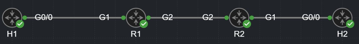
Imagine you configured a simple point-to-point GRE tunnel across these two routers - think about how that GRE tunnel works. On each end, you specify the source and destination IP addresses of the tunnel. If you send traffic through the tunnel from R1, the traffic is always sent to the opposite tunnel endpoint (R2) as defined by the aforementioned tunnel destination, regardless of the destination of the inner (tunneled) traffic.
Now, imagine that you have VRFs H1 and H2 configured on both R1 and R2. Let’s say you put R1’s side of the tunnel into VRF H1 and R2’s side of the tunnel into VRF H2. Let’s think about what happens here.
Suppose you have traffic coming in on R1’s Gig2, an interface that belongs to VRF H1, that is destined to 10.0.2.0/24. Suppose the routing table for VRF H1 routes that traffic out through the tunnel. Remember, the tunnel unconditionally places the outer IP encapsulation and sends it to R2, our opposite tunnel endpoint.
When R2 receives it, think back to the process we discussed in the previous section. R2 examines the VRF of the ingress interface of this traffic (the tunnel interface) and determines that the tunnel interface, and, consequently, the traffic itself, is part of VRF H2. R2 then performs a routing lookup for the destination of the traffic inside of VRF H2’s routing table. Because R2’s Gig2, the interface that 10.0.2.0/24 is directly connected to, is a member of VRF H2, R2 finds this directly connected route and sends the traffic on its merry way out of Gig2.
We can see that this is the case with this configuration and ping below!
! R1 configuration
interface GigabitEthernet1
 vrf forwarding H1
 ip address 10.0.1.1 255.255.255.0
 negotiation auto
!
interface GigabitEthernet2
 ip address 10.0.0.1 255.255.255.0
 negotiation auto
!
interface Tunnel0
 vrf forwarding H1
 ip address 192.168.1.1 255.255.255.0
 tunnel source 10.0.0.1
 tunnel destination 10.0.0.2
!
ip route vrf H1 10.0.2.0 255.255.255.0 192.168.1.2
! R2 configuration
interface GigabitEthernet1
 vrf forwarding H2
 ip address 10.0.2.1 255.255.255.0
 negotiation auto
!
interface GigabitEthernet2
 ip address 10.0.0.2 255.255.255.0
 negotiation auto
!
interface Tunnel0
 vrf forwarding H2
 ip address 192.168.1.2 255.255.255.0
 tunnel source 10.0.0.2
 tunnel destination 10.0.0.1
!
ip route vrf H2 10.0.1.0 255.255.255.0 192.168.1.1
H1#ping 10.0.2.2
Type escape sequence to abort.
Sending 5, 100-byte ICMP Echos to 10.0.2.2, timeout is 2 seconds:
!!!!!
Success rate is 100 percent (5/5), round-trip min/avg/max = 4/6/8 ms
By the way, you could have done this without any GRE tunnels by just using the physical connection between R1 and R2 - R1’s GigabitEthernet1 goes into VRF H1 and R2’s GigabitEthernet1 goes into VRF H2! However, I prefer the tunnel analogy for thinking about VASI pairs, as VASI pairs are inherently point-to-point, just like a P2P GRE tunnel.
Did you catch what happened here? You just sent traffic from an interface in VRF H1…to an interface in VRF H2. No route leaking involved! Magic! Smokes and mirrors!
…no, not really! What we did is fairly simple - we just used the tunnel as a conduit between the VRFs by placing each end in a different VRF! Make sure you fully understand how this works - it’s super important to understanding VASI!
That’s Enough GRE!
How is this related to our scenario? The only difference between this scenario and the previous one is an extra router! Same networks (10.0.1.0/24 and 10.0.2.0/24), same requirement (ping between 10.0.1.0/24 and 10.0.2.0/24). We’re just working with a single router terminating both VRFs. It’s essentially the same situation in both cases!
The problem is that we can’t run a GRE tunnel where our tunnel endpoints are both on the same router. This is exactly the problem that VASI pairs solve! A VASI pair is an internal tunnel between the vasileft interface and the vasiright interface.
We can do the exact same thing that we did with the GRE tunnel using VASI interfaces! How? By placing the vasileft interface in VRF H1 and the vasiright interface in VRF H2!
Side note: You can also flip-flop the order around - left and right don’t have any directional significance beyond indicating opposing ends of the internal tunnel. That said, the standard convention is to think of your initiating traffic flows as going left to right and vice versa for your returning traffic flows.
One more thing before we actually try it out! In the case of a GRE tunnel, we need to configure tunnel sources and destinations to tell the tunnel interface where the other end. You can have multiple VASI pairs on a single device, so how does a vasileft interface identify its paired vasiright interface?
The number! Each vasileft and vasiright interface has a number at the end of it, the lowest being 1. This number is the number of the VASI pair and must be consistent between the left and right interfaces. The “internal tunnel”, as such, for a VASI pair numbered X goes between vasileftX and vasirightX.
Configuring a VASI Pair
Let’s do this!
The configuration for a VASI pair is remarkably simple. All we need to do is define the left and right interfaces, place each in their respective VRFs (or global), and define an IP network.
The significance of the IP network here is just to have addresses on each interface that we can leverage later for our routing next hops. As such, we can just use a /31 since you’ll never need more than two IP addresses in a VASI pair; this helps us utilize as little of our address space as possible. Personally, I tend to use addresses in the 192.0.2.0/24 range since that is reserved as a test network and usually isn’t used in many other places, but you can use whatever addressing scheme you’d like here!
interface vasileft1
vrf forwarding H1
ip address 192.0.2.0 255.255.255.254
interface vasiright1
vrf forwarding H2
ip address 192.0.2.1 255.255.255.254
That’s it! That’s a functional VASI pair!
R1#show vasi pair status

Pair name     Left state             Right state            Pair state
------------------------------------------------------------------------------
VASIPair1     up                     up                     up
R1#sh ip int br | i vasi
vasileft1              192.0.2.0       YES manual up                    up
vasiright1             192.0.2.1       YES manual up                    up
Notice that we can ping the IP address of the left interface from the VRF of the right interface and vice versa:
R1#ping vrf H1 192.0.2.1
Type escape sequence to abort.
Sending 5, 100-byte ICMP Echos to 192.0.2.1, timeout is 2 seconds:
!!!!!
Success rate is 100 percent (5/5), round-trip min/avg/max = 1/4/20 ms
R1#ping vrf H2 192.0.2.0
Type escape sequence to abort.
Sending 5, 100-byte ICMP Echos to 192.0.2.0, timeout is 2 seconds:
!!!!!
Success rate is 100 percent (5/5), round-trip min/avg/max = 1/1/1 ms
We just achieved inter-VRF reachability! Yes, that easily!
Maps, Route Me To The Nearest VRF!
Let’s look at the routing table for VRF H1 right now:
R1#sho ip route vrf H1 | b ^G
Gateway of last resort is not set

      10.0.0.0/8 is variably subnetted, 2 subnets, 2 masks
C        10.0.1.0/24 is directly connected, GigabitEthernet1
L        10.0.1.1/32 is directly connected, GigabitEthernet1
      192.0.2.0/24 is variably subnetted, 2 subnets, 2 masks
C        192.0.2.0/31 is directly connected, vasileft1
L        192.0.2.0/32 is directly connected, vasileft1
You’ll notice that we have the directly connected route for the H1-R1 network (10.0.1.0/24) and the network of the VASI pair. Remember our goal though - we want to route to the 10.0.2.0/24 network from VRF H1 without using route leaking. So, let’s do that!
Just like the GRE tunnel example, our goal is going to be to force all of this traffic over the “internal tunnel” that is created by our VASI pair. Routing our traffic from vasileft1 in VRF H1 to vasiright1 in VRF H2 is going to achieve the goal we mentioned above: ensure that the ingress interface of the traffic (vasiright1) and the egress interface of the traffic (GigabitEthernet2) are in the same VRF (H2).
For this example, we’ll use static routes for some simple routing. We’ll look at something better than static (cough dynamic cough) in a moment! For now, we can compose our static route in one of three ways:
- Next-hop only - specify the IP address of the VASI interface in the OTHER VRF as your next hop
- Interface only - specify the VASI interface in the LOCAL VRF as your egress interface
- Both - a combination of 1 and 2; creates a fully-specified route
Using any of the above methods, our result will be the same: the traffic gets routed to the opposite VASI interface (and consequently, the opposite VRF.)
ip route vrf H1 10.0.2.0 255.255.255.0 vasileft1 192.0.2.1
ip route vrf H2 10.0.1.0 255.255.255.0 vasiright1 192.0.2.0
Notice that the next hop for the static route in VRF H1 is 192.0.2.1 (the IP address of vasiright1) and the egress interface is vasileft1. The opposite is true for the static route created in VRF H2.
Remember the routing path - we want to push the traffic out of the vasileft interface and send it towards the vasiright interface. If this is unintuitive, I get it! Think of it this way - the next hop tells us where we want to go, the egress interface tells us how to get there. We want to get to the vasiright interface (hence the 192.0.2.1 next hop) via the vasileft interface.
The configuration above leverages fully-specified static routes, in order to demonstrate the values we need for both the egress interface and the next hop. Keep in mind, this is technically overkill in this scenario - you could leave out either the egress interface or the next hop and it would still work completely fine!
Let’s Check Our Work!
Let’s do a quick routing table check:
R1#sh ip route vrf H1 | b ^G
Gateway of last resort is not set

      10.0.0.0/8 is variably subnetted, 3 subnets, 2 masks
C        10.0.1.0/24 is directly connected, GigabitEthernet1
L        10.0.1.1/32 is directly connected, GigabitEthernet1
S        10.0.2.0/24 [1/0] via 192.0.2.1, vasileft1
      192.0.2.0/24 is variably subnetted, 2 subnets, 2 masks
C        192.0.2.0/31 is directly connected, vasileft1
L        192.0.2.0/32 is directly connected, vasileft1
Notice that we now have a route to the 10.0.2.0/24 network via the vasileft interface, which steers the traffic into VRF H2.
Once the traffic pops out of the other side of this internal tunnel (the vasiright interface) and into VRF H2, if we examine the routing table for VRF H2:
R1#sh ip route vrf H2 | b ^G
Gateway of last resort is not set

      10.0.0.0/8 is variably subnetted, 3 subnets, 2 masks
S        10.0.1.0/24 [1/0] via 192.0.2.0, vasiright1
C        10.0.2.0/24 is directly connected, GigabitEthernet2
L        10.0.2.1/32 is directly connected, GigabitEthernet2
      192.0.2.0/24 is variably subnetted, 2 subnets, 2 masks
C        192.0.2.0/31 is directly connected, vasiright1
L        192.0.2.1/32 is directly connected, vasiright1
You’ll notice the 10.0.2.0/24 connected route that pushes us to the final stop, out of the GigabitEthernet2 interface!
You’ll also notice the other static route we created here, which will allow the return traffic destined to H1 to swing back around to H1 via the reverse of the process we just discussed!
And a quick ping to confirm that this is all working:
H1#ping 10.0.2.2
Type escape sequence to abort.
Sending 5, 100-byte ICMP Echos to 10.0.2.2, timeout is 2 seconds:
!!!!!
Success rate is 100 percent (5/5), round-trip min/avg/max = 4/4/6 ms
Yep! We’ve yet to see the best part though… If you didn’t believe me that this is really an internal tunnel:
H1#traceroute 10.0.2.2 numeric
Type escape sequence to abort.
Tracing the route to 10.0.2.2
VRF info: (vrf in name/id, vrf out name/id)
  1 10.0.1.1 3 msec 1 msec 1 msec
  2 192.0.2.1 4 msec 1 msec 1 msec
  3 10.0.2.2 6 msec *  5 msec
The VASI pair even shows up in traceroute output, which means that IOS is decrementing the TTL as the traffic is routed through the VASI pair! This is what you would see in the case of an entirely separate routing hop - we just have one router here!
We’re NAT Done Yet! - Configuring NAT on VASI Interfaces
We’ve gotten basic inter-VRF reachability to work over a VASI pair. Can this thing do anything else? You bet it can!
You can treat the VASI pair just as any other tunnel for most purposes. There are some caveats to this rule, but those are the exceptions and not worth specifically enumerating here. Because you can treat VASI interfaces as regular interfaces, you can run services between VRFs that are traditionally unaware of inter-VRF communication just by hooking those services into the VASI interfaces, since the VASI interfaces abstract all of the details regarding the inter-VRF forwarding at the data plane level. This is where the true power of VASI lies.
The classic example is NAT (though there are others, like IOS ZBFW.) So, let’s do some inter-VRF NAT here!
Preparation
What we’ll do for this demo is remove the default route from H2:
H2(config)#no ip route 0.0.0.0 0.0.0.0 10.0.2.1
H2(config)#end
H2#sh ip route | b ^G
Gateway of last resort is not set

      10.0.0.0/8 is variably subnetted, 2 subnets, 2 masks
C        10.0.2.0/24 is directly connected, GigabitEthernet0/0
L        10.0.2.2/32 is directly connected, GigabitEthernet0/0
Without a route back towards H1 on H2, our attempts to ping from H1 to H2 don’t exactly go to plan:
H1#ping 10.0.2.2
Type escape sequence to abort.
Sending 5, 100-byte ICMP Echos to 10.0.2.2, timeout is 2 seconds:
.....
Success rate is 0 percent (0/5)
Now, the classic trick to get around a lack of routing reachability for return traffic is to translate the source IP address of the initial traffic to an IP address for which the destination host does have a route!
Since H2 only has a connected route for the 10.0.2.0/24 network, our translated source IP address needs to be in that subnet. Let’s pick 10.0.2.42 - after all, it is this subnet’s answer to life, the universe, and everything! 😆
NAT? How?
Getting to the actual NAT component of this puzzle, there are two main approaches that we can use for performing NAT across a VASI pair:
- NAT in the source VRF - this method performs NAT on the traffic before pushing the traffic through the VASI pair. As such, the original ingress interface becomes the NAT inside interface and the VASI interface becomes the NAT outside interface.
- NAT in the destination VRF - this method performs NAT on the traffic after pushing the traffic through the VASI pair. As such, the VASI interface becomes the NAT inside interface and the actual egress interface becomes the NAT outside interface.
As you think about the inside/outside roles of the various interfaces in both approaches, keep in mind the classic rule of IOS NAT: your traffic must be routed between an inside interface and an outside interface for it to qualify for translation in the first place.
Both approaches are equally valid in different situations! The main difference between the two approaches revolves around the routes that we need to have in the destination VRF.
If you NAT the traffic before the traffic is pushed over to the destination VRF via the VASI pair, the destination VRF only ever sees the translated IP address. As such, it doesn’t need routes to the network of the original (un-translated) IP address - it only needs routes to the translated IP address.
By contrast, if you NAT the traffic after it is pushed over to the destination VRF, the destination VRF has to handle the original, un-translated IP address, meaning that it needs to be able to route that address back to the original VRF to properly forward the return traffic.
In this case, it doesn’t matter…so we’ll demonstrate both! Keep in mind that throughout this example, the “original” or “source” VRF is H1 and the “destination” VRF is H2.
Some Configurations to Get Out of the Way First…
Let’s get some groundwork out of the way before we take a look at the NAT config! Firstly, we’ll need to create an ACL to match the interesting traffic for our NAT rule:
ip access-list extended H1
 10 permit ip host 10.0.1.2 host 10.0.2.2
Next, we’ll want to create a NAT pool containing the address we want to translate to:
ip nat pool TRANSLATED 10.0.2.42 10.0.2.42 prefix-length 24
Do note that it’s a bad idea to translate directly onto the IP address of the VASI interfaces. Generally speaking, you’ll want to use a NAT pool here. That said, it is worth noting that, in the case of method 2, you can technically use the interface keyword in your NAT translation rule to use the interface IP of your outside (egress) interface.
Method 1 - Translation in the Original VRF (H1)
Our real ingress interface here is GigabitEthernet1 (the interface connected to H1.) Our egress interface, from VRF H1’s perspective, is vasileft1, since this is the interface we are using to route to VRF H2. As such, GigabitEthernet1 is our inside interface and vasileft1 is our outside interface. Let’s configure them with those roles!
interface GigabitEthernet1
 ip nat inside
interface vasileft1
 ip nat outside
From there, we’re ready to configure our actual translation rule! In this case, we’ll enable port overloading (PAT), though this is not a requirement.
ip nat inside source list H1 pool TRANSLATED vrf H1 overload
The important part here, as far as inter-VRF NAT (VASI NAT) goes, is that the rule references our H1 “original” VRF.
While all of our NAT configuration is here, if we try our ping again, it will still fail!
H1#ping 10.0.2.2
Type escape sequence to abort.
Sending 5, 100-byte ICMP Echos to 10.0.2.2, timeout is 2 seconds:
.....
Success rate is 0 percent (0/5)
Why could this be? We have the translation working properly!
R1#sho ip nat translation
Pro  Inside global         Inside local          Outside local         Outside global
icmp 10.0.2.42:10          10.0.1.2:10           10.0.2.2:10           10.0.2.2:10
Let’s examine the routing table for the H2 VRF:
R1#sho ip route vrf H2 | b ^G
Gateway of last resort is not set

      10.0.0.0/8 is variably subnetted, 3 subnets, 2 masks
S        10.0.1.0/24 [1/0] via 192.0.2.0, vasiright1
C        10.0.2.0/24 is directly connected, GigabitEthernet2
L        10.0.2.1/32 is directly connected, GigabitEthernet2
      192.0.2.0/24 is variably subnetted, 2 subnets, 2 masks
C        192.0.2.0/31 is directly connected, vasiright1
L        192.0.2.1/32 is directly connected, vasiright1
Ahh…we’re getting closer to the answer. Hey, VRF H2? Quick question: where do you think 10.0.2.42 lives?
R1#sho ip route vrf H2 10.0.2.42

Routing Table: H2
Routing entry for 10.0.2.0/24
  Known via "connected", distance 0, metric 0 (connected, via interface)
  Routing Descriptor Blocks:
  * directly connected, via GigabitEthernet2
      Route metric is 0, traffic share count is 1
Heh. Heh. That’s a bit of a problem! Let’s fix that with a quick static route to nudge the H2 VRF table into realizing that 10.0.2.42 doesn’t quite live where it thinks it does!
ip route vrf H2 10.0.2.42 255.255.255.255 vasiright1 192.0.2.0
R1#sho ip route vrf H2 10.0.2.42

Routing Table: H2
Routing entry for 10.0.2.42/32
  Known via "static", distance 1, metric 0
  Routing Descriptor Blocks:
  * 192.0.2.0, via vasiright1
      Route metric is 0, traffic share count is 1
H1#ping 10.0.2.2
Type escape sequence to abort.
Sending 5, 100-byte ICMP Echos to 10.0.2.2, timeout is 2 seconds:
!!!!!
Success rate is 100 percent (5/5), round-trip min/avg/max = 4/5/6 ms
Nice, that’s a lot better! Now that the routing table for the H2 VRF knows that it needs to route traffic destined to 10.0.2.42 (our translated source IP address) back to VRF H1 to be un-translated, everything works!
Method 2 - Translation in the Destination VRF (H2)
Remember: we are performing NAT in the destination VRF, after we push the traffic over the VASI pair. This means that VRF H2 sees the un-translated IP addresses from VRF H1.
As such, the ingress interface for the traffic is vasiright1 in this case, as that is the VASI interface inside of VRF H2. This interface, therefore, becomes the NAT inside interface.
The egress interface for the traffic is GigabitEthernet2, as this is the interface we want to route our traffic out towards. As such, this needs to be configured as our NAT outside interface.
Without further ado, meet your newly classified interfaces!
interface vasiright1
 ip nat inside
interface GigabitEthernet2
 ip nat outside
Let’s go ahead and create our new translation rule now!
ip nat inside source list H1 pool TRANSLATED vrf H2 overload
Notice that the difference between this translation rule and the previous rule is the VRF. Because we are performing the translation in the destination VRF, we need to specify the H2 VRF inside of our translation rule. Otherwise, the command is the exact same!
Let’s go ahead and try our ping again!
H1#ping 10.0.2.2
Type escape sequence to abort.
Sending 5, 100-byte ICMP Echos to 10.0.2.2, timeout is 2 seconds:
!!!!!
Success rate is 100 percent (5/5), round-trip min/avg/max = 4/5/6 ms
Hey, it worked this time, no questions asked! But wait, why didn’t we need to create a route for the return traffic like we did in method 1? Ahhh. Let’s talk about that.
If we check out the routing table for VRF H2:
R1#sho ip route vrf H2 | b ^G
Gateway of last resort is not set

      10.0.0.0/8 is variably subnetted, 3 subnets, 2 masks
S        10.0.1.0/24 [1/0] via 192.0.2.0, vasiright1
C        10.0.2.0/24 is directly connected, GigabitEthernet2
L        10.0.2.1/32 is directly connected, GigabitEthernet2
      192.0.2.0/24 is variably subnetted, 2 subnets, 2 masks
C        192.0.2.0/31 is directly connected, vasiright1
L        192.0.2.1/32 is directly connected, vasiright1
Remember that the translation happens inside of VRF H2. As such, the return traffic is also un-translated and returned to its original source IP address (the 10.0.1.2 IP address of H1) prior to being sent back through the VASI pair to VRF H1. This is a consequence of the NAT order of operations. Because the routing lookup is actually done using the 10.0.1.2 IP address (not the 10.0.2.42 translated IP address), the static route we configured previously in this post did the job for us.
This reliance on a route for the original, un-translated address is exactly why you sometimes want to be hesitant about using method 2. Admittedly, method 2 is arguably simpler, in the sense that your routing is very similar to a scenario without NAT (i.e., just route VRF H1 networks to VRF H1 and you’re golden). No need to think about routing the translated IP addresses back to the original VRF, as we did in method 1.
However, the trap is in the details - overlapping IP ranges. This is especially a problem if you have more than two VRFs here. Suppose you have 5 VRFs that H2 is responsible for translating. Those 5 VRFs could have overlapping IP ranges, which is a big problem if you are handling the un-translated networks inside of the single H2 VRF routing table. In that scenario, you would be forced to adopt method 1. In simpler scenarios, such as this one, either works.
Okay, Fine, Maybe Route Leaking Isn’t So Bad After All…
Throughout the previous sections, we’ve been looking at VASI as though it’s an alternative to route leaking! Let’s throw the two into a mixing bowl and see what we can do!
Did you know we can actually route leak USING VASI interfaces? Think back to our GRE tunnel example. Instead of using static routes to push traffic inside of the H1 VRF destined to 10.0.2.0/24 over the tunnel, we could have run a dynamic routing protocol (e.g., OSPF or BGP) to advertise the routes over the tunnel itself. That would have the same result, since the next hop of the routes received on R1 would be R2’s tunnel endpoint IP address.
Before we do anything, let’s first remove the static routes we’ve been relying on.
R1(config)#no ip route vrf H1 10.0.2.0 255.255.255.0 192.0.2.1 vasileft1
R1(config)#no ip route vrf H2 10.0.1.0 255.255.255.0 192.0.2.0 vasiright1
H1#ping 10.0.2.2
Type escape sequence to abort.
Sending 5, 100-byte ICMP Echos to 10.0.2.2, timeout is 2 seconds:
.....
Success rate is 0 percent (0/5)
Perfect! That looks broken enough!
OSPF
Now, you may be thinking - isn’t a VASI pair just an internal tunnel? Could you just run a routing protocol adjacency over the VASI pair-
router ospf 101 vrf H1
 capability vrf-lite
router ospf 102 vrf H2
 capability vrf-lite
interface vasileft1
 ip ospf 101 area 0
interface vasiright1
 ip ospf 102 area 0
R1#sho ip ospf nei

Neighbor ID     Pri   State           Dead Time   Address         Interface
192.0.2.0         0   FULL/  -        00:00:39    192.0.2.0       vasiright1
192.0.2.1         0   FULL/  -        00:00:38    192.0.2.1       vasileft1
Of course you can. Of course.
We’ve been using static routes to push traffic over our VASI pair this entire time! No more! Time for dynamic routing to reclaim the crown! Muahahaha.
Now, one important thing to notice about the configuration above is the presence of two separate OSPF routing processes. When you configure a routing protocol adjacency between the VASI pair interfaces, you need to remember that each interface is in a different VRF.
Since you can’t mix and match interfaces across VRFs within a particular routing process, you need to configure two routing processes - one for each VRF. By doing this, you are effectively forming a routing adjacency across the routing processes.
EIGRP
You’ve seen what that looks like for OSPF! Here’s EIGRP:
router eigrp NAMED
 !
 address-family ipv4 unicast vrf H1 autonomous-system 1
  !
  topology base
  exit-af-topology
  network 192.0.2.0 0.0.0.0
 exit-address-family
 !
 address-family ipv4 unicast vrf H2 autonomous-system 1
  !
  topology base
  exit-af-topology
  network 192.0.2.1 0.0.0.0
 exit-address-family
R1#sho eigrp address-family ipv4 vrf H1 neighbors
EIGRP-IPv4 VR(NAMED) Address-Family Neighbors for AS(1)
           VRF(H1)
H   Address                 Interface              Hold Uptime   SRTT   RTO  Q  Seq
                                                   (sec)         (ms)       Cnt Num
0   192.0.2.1               vl1                      11 00:00:22    3   100  0  2
R1#sho eigrp address-family ipv4 vrf H2 neighbors
EIGRP-IPv4 VR(NAMED) Address-Family Neighbors for AS(1)
           VRF(H2)
H   Address                 Interface              Hold Uptime   SRTT   RTO  Q  Seq
                                                   (sec)         (ms)       Cnt Num
0   192.0.2.0               vr1                      13 00:00:25    1   100  0  2
Make sure those AS numbers match! Also, notice that this is named mode EIGRP. This is also possible, albeit less elegant in its configuration, with the classic numbered EIGRP!
BGP
And, last but not least, here’s BGP! Note that we need to configure RDs here under our VRFs, since BGP won’t run in a VRF without an RD. Since we’re only using VRF-lite here though, it doesn’t matter what the RDs are!
vrf definition H1
 rd 1:1
vrf definition H2
 rd 1:2
router bgp 1
 bgp router-id 10.10.10.10
 bgp log-neighbor-changes
 !
 address-family ipv4 vrf H1
  bgp router-id 1.1.1.1
  neighbor 192.0.2.1 remote-as 1
  neighbor 192.0.2.1 activate
 exit-address-family
 !
 address-family ipv4 vrf H2
  bgp router-id 1.1.1.2
  neighbor 192.0.2.0 remote-as 1
  neighbor 192.0.2.0 activate
 exit-address-family
R1#sho bgp vpnv4 unic all sum
BGP router identifier 10.10.10.10, local AS number 1
BGP table version is 1, main routing table version 1

Neighbor        V           AS MsgRcvd MsgSent   TblVer  InQ OutQ Up/Down  State/PfxRcd
192.0.2.0       4            1       4       4        1    0    0 00:01:08        0
192.0.2.1       4            1       4       4        1    0    0 00:01:08        0
Something interesting to note for BGP is that everything runs under one routing process with multiple address families. As such, you need to make sure that you set at least two unique router IDs:
- Under the
router bgpprocess level - Under the
address-family <AF> vrf <VRF>VRF level
I’d recommend just setting a static BGP RID across both of the VRFs to be safe.
Wait, What Does the RID Have to Do With Anything Again?
Across all of the routing protocols, the RID is an incredibly important setting. Remember, you’re forming a relationship across two routing processes/address families on the same router, so a duplicate RID is a possibility if you either have overlapping IP addresses across both VRFs that are automatically selected as the RID or manually set a duplicate RID.
With OSPF and BGP, your neighborship will refuse to form. With EIGRP, it will form (technically), but you can’t accept routes due to loop prevention. Soooo, unless you like having neighborships that are there purely for show, set the RID! 😉
You’ll notice we didn’t have to think about this for OSPF and EIGRP, though. That’s because BGP needs a process-level RID, which requires at least one global interface with an IP address. Without this, the process doesn’t start correctly; you can form peerings but you can’t do any show commands. Once you set a process-level RID though, all address families inherit it, hence the need for at least one VRF to have an address family-level override. For OSPF and EIGRP, they are happy to grab a VRF-specific RID for each VRF automatically.
Let’s Advertise Some Networks Now!
After you get the adjacency up, just ensure that the appropriate networks are advertised across the adjacency in each VRF’s routing process. Once the routes are advertised across the routing adjacency, boom! Each VRF learns the other VRF’s route(s) in its local routing table with the VASI interface inside of the VRF as the egress interface and its opposing VASI interface as the next hop.
Let’s try it with OSPF! Remember to make sure you activate the interface under the correct OSPF process, based on the VRF of the interface!
interface GigabitEthernet1
 ip ospf 101 area 0
interface GigabitEthernet2
 ip ospf 102 area 0
R1#sho ip route vrf H1 ospf | b ^G
Gateway of last resort is not set

      10.0.0.0/8 is variably subnetted, 3 subnets, 2 masks
O        10.0.2.0/24 [110/2] via 192.0.2.1, 00:21:08, vasileft1
R1#sho ip route vrf H2 ospf | b ^G
Gateway of last resort is not set

      10.0.0.0/8 is variably subnetted, 3 subnets, 2 masks
O        10.0.1.0/24 [110/2] via 192.0.2.0, 00:21:20, vasiright1
Awesome! We’re learning routes! What about EIGRP?
router eigrp NAMED
 !
 address-family ipv4 unicast vrf H1 autonomous-system 1
  !
  network 10.0.1.1 0.0.0.0
 exit-address-family
 !
 address-family ipv4 unicast vrf H2 autonomous-system 1
  !
  network 10.0.2.1 0.0.0.0
 exit-address-family
R1#sh ip route vrf H1 eigrp | b ^G
Gateway of last resort is not set

      10.0.0.0/8 is variably subnetted, 3 subnets, 2 masks
D        10.0.2.0/24 [90/10752] via 192.0.2.1, 00:01:38, vasileft1
R1#sh ip route vrf H2 eigrp | b ^G
Gateway of last resort is not set

      10.0.0.0/8 is variably subnetted, 3 subnets, 2 masks
D        10.0.1.0/24 [90/10752] via 192.0.2.0, 00:01:58, vasiright1
Hey, routes! You decided to join the party! And…last, but not least, BGP!
router bgp 1
 !
 address-family ipv4 vrf H1
  network 10.0.1.0 mask 255.255.255.0
 exit-address-family
 !
 address-family ipv4 vrf H2
  network 10.0.2.0 mask 255.255.255.0
 exit-address-family
R1#sho ip route vrf H1 bgp | b ^G
Gateway of last resort is not set

      10.0.0.0/8 is variably subnetted, 3 subnets, 2 masks
B        10.0.2.0/24 [200/0] via 192.0.2.1, 00:00:13
R1#sho ip route vrf H2 bgp | b ^G
Gateway of last resort is not set

      10.0.0.0/8 is variably subnetted, 3 subnets, 2 masks
B        10.0.1.0/24 [200/0] via 192.0.2.0, 00:00:28
That easy! The result here, across all three protocols (and the other routing protocols we didn’t show!), is exactly the same as our static route example, except you’ll notice the distinct lack of static routes! Begone, statics!
Compared to traditional route leaking, using dynamic routing over VASI interfaces means you aren’t required to configure route targets and BGP even if you only intend to use VRF-lite! That said, I’m sure BGP would love to join the party regardless!
And it wouldn’t be a complete routing experiment if we didn’t wrap it up with a nice !!!!! from a successful ping!
H1#ping 10.0.2.2
Type escape sequence to abort.
Sending 5, 100-byte ICMP Echos to 10.0.2.2, timeout is 2 seconds:
!!!!!
Success rate is 100 percent (5/5), round-trip min/avg/max = 4/6/9 ms
Conclusion
VRF-Aware Software Infrastructure (VASI) pairs are a great tool for managing inter-VRF communications on a router! Compared to previous methods of configuring inter-VRF functionality, such as inter-VRF NAT, working with VASI pairs is natural and doesn’t introduce any significant paradigm shifts from the workflows that you’ve already established for other types of interfaces! Plus, they handle NAT real well!
All of the inter-VRF goodness is handled for you by the IOS-XE platform (thank you, IOS-XE!!!) The bottom line is: don’t be scared of VASI - it’s here to help!